
Videos from Interventional Cardiac Electrophysiology
Video 4.1
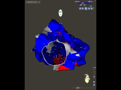
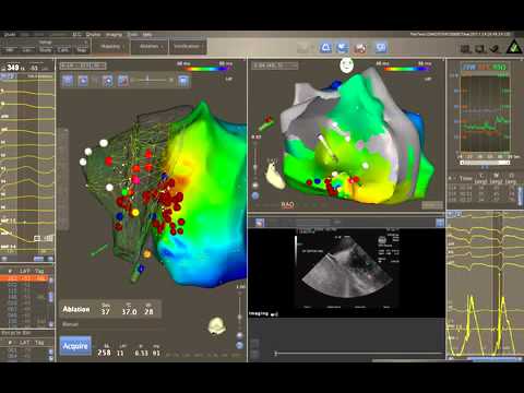
Video 4.1 Left anterior oblique projection of the right atrium with a barrel view down the tricuspid valve. Activation mapping reveals bidirectional block following cavotricuspid isthmus ablation. The lesion set is depicted by three-dimensional red circles.
Video 7.1
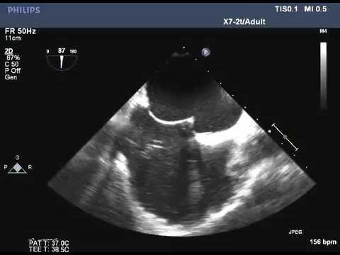
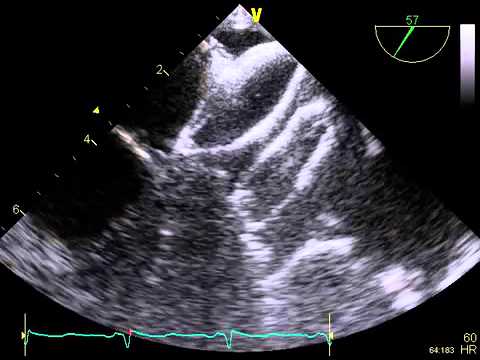
Video 7.1 Bicaval view from transesophageal echocardiography showing the atrial septum.
Video 7.2
Video 7.2 Tenting of the atrial septum seen with the transseptal needle.
Video 7.3
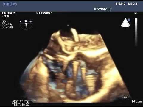
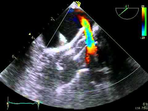
Video 7.3 Real-time three-dimensional (3D) imaging is used more frequently to help guide transseptal catheter placement. This is an example of real-time 3D imaging showing the transseptal catheter in the left atrium.
Video 8.1

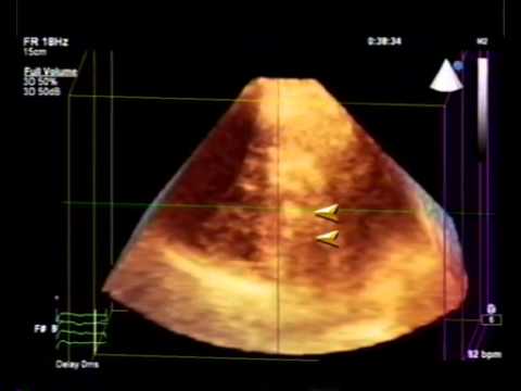
Video 8.1 (Figure 8.4A, Part 1) Video from another patient shows a thrombus (arrowhead) in the left atrial appendage (LAA) viewed in the 2D aortic short axis view. MPA = main pulmonary artery. A similar image is then acquired in 3 dimensions and the thrombus cropped to show absence of clot lysis.
Video 8.2
Video 8.2 (Figure 8.4A, Part 2) Video from a different patient shows 2 prominent linear pectinate muscles (arrowheads), which, when viewed in short axis, mimic clots in the LA appendage. Use of 3D echocardiography with cropping of datasets clarifies their true nature. AV = aortic valve.
Video 8.3

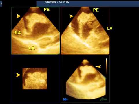
Video 8.3 (Figure 8.5A) Video shows the relationship of RAA to ascending aorta (AA) and pulmonary artery (PA). The bubble study shows contrast entering the RAA following an intravenous injection. The large echo-free space around the RAA represents pericardial effusion. PE = pericardial effusion. Source: Reproduced with permission from Patel V, et al.
Video 8.4

Video 8.4 (Figure 8.9A) Source: Yelamanchili P, et al.33
Video 8.5

Video 8.5 (Figure 8.9B) Source: Yelamanchili P, et al.33
Video 8.6
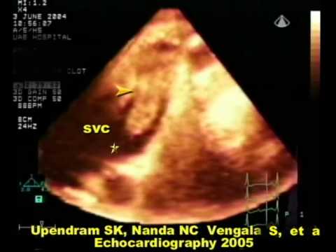
Video 8.6 (Figure 8.13) The asterisk in the video clip denotes a mobile component of the thrombus, particularly prone to embolization. Source: Reproduced with permission from Upendram S, et al.51
Video 8.7
Video 8.7 (Figure 8.14) Source: Reproduced with permission from Hernandez CM, et al.53
Video 9.1

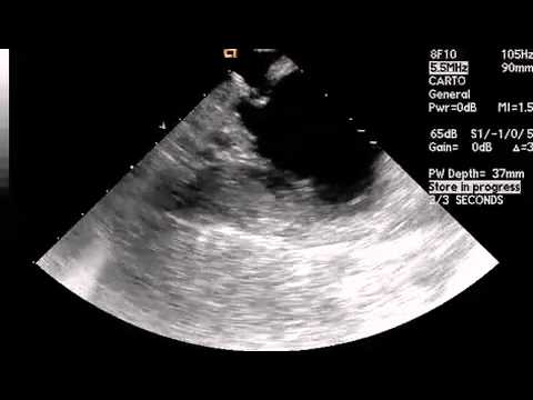
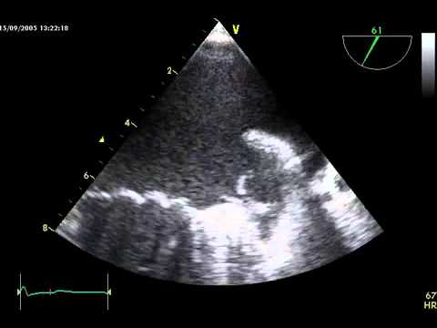
Video 9.1 ICE video of left atrial anatomy in view of the mitral valve. At the apex of the ICE image sector, the right atrial chamber is seen. Below this appears the thin-walled fossa ovalis, below which is seen the left atrium. At 9 o'clock on the left atrium, the coronary sinus is seen in cross-section.
Video 9.2
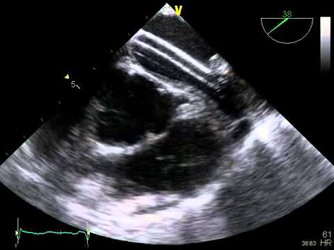
Video 9.2 ICE video of tenting of fossa ovalis prior to transseptal puncture. The tip of the transseptal apparatus is seen abutting the fossa ovalis, which leads to "tenting" of the fossa (see also Figures 9.6 and 9.11).
Video 9.3

Video 9.3 ICE video of transseptal puncture using a radiofrequency needle. At the apex of the ICE image sector, the right atrial chamber is seen. Below this appears the thin-walled fossa ovalis, below which is seen the left atrium. The tip of the transseptal puncture apparatus is seen "tenting" the fossa ovalis.
Video 9.4
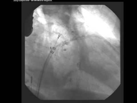
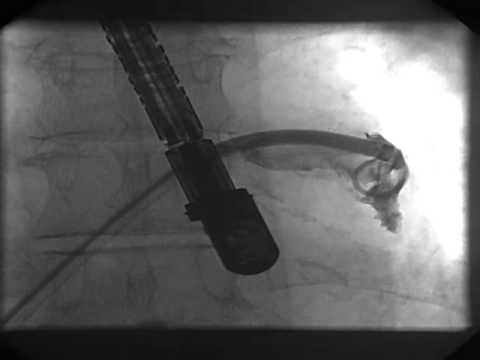
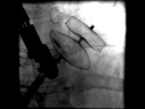
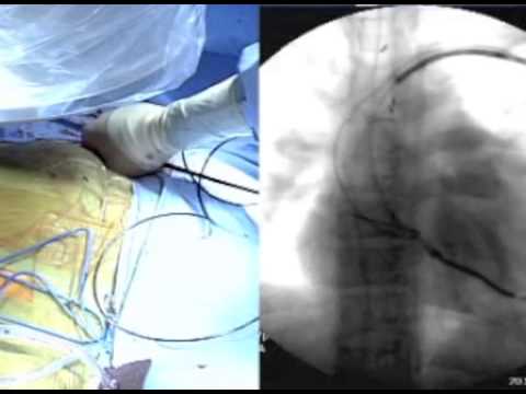
Video 9.4 Cine angiogram of left-atrial appendage occlusion device deployment. To start, the device is still attached to the delivery catheter. At 00:08, after positioning has been optimized, the device is deployed and the delivery catheter retracted into the delivery sheath (see Figure 9.9).
Video 9.5

Video 9.5 Animation showing merged preprocedural computed tomogram of left atrial anatomy with intraprocedurally acquired 3D composite of left atrial anatomy based on a series of 2D ICE images (see Figure 9.10).
Video 10.1

Video 10.1 (Figure 10.3) Clip file during AF ablation, using a registered LA CT reconstruction fused with the 3D map. Note the position of the mapping catheter moving from the left inferior pulmonary vein (LIPV) to left superior pulmonary vein (LSPV) and the slight misregistration evidenced by the appearance of the mapping catheter tip outside of the LSPV endocardial contours.
Video 10.2
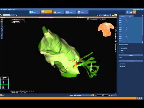
Video 10.2 (Figure 10.7) Ablation for septal VT using an intracardiac ultrasound shell (CartoSound, mesh) integrated with a 3D electroanatomic map. The colored points represent pace-mapping sites for the clinical VT.
Video 10.3
Video 10.3 (Figure 10.9) 3D electroanatomic map (EnSite Velocity) fused with a CT reconstruction of the right atrium to guide systemic ventricular lead implantation in a patient with advanced heart failure with L-transposition of the great arteries and dextrocardia. As a result of the greatly distorted cardiac anatomy, a catheter with a distal bipole and a 7-Fr lumen (CPS Luminary, St.
Video 11.1

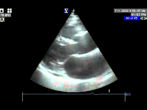
Video 11.1 Horizontal long-axis MRI steady-state, free precession cine sequence showing extensive apical hypertrophy.
Video 11.2
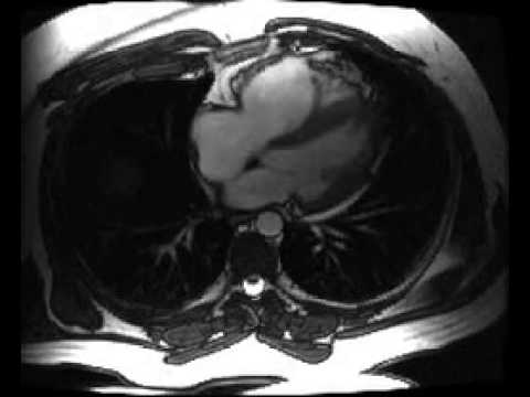
Video 11.2 Axial MRI steady-state, free precession cine sequence showing right ventricular dilation and basal dyskinesis.
Video 16.1
Video 16.1 Echocardiographic exclusion of alternative cardioembolic sources.
Video 16.2
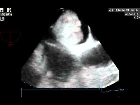
Video 16.2 Echocardiographic exclusion of alternative cardioembolic sources.
Video 16.3

Video 16.3 Echocardiographic exclusion of alternative cardioembolic sources.
Video 16.4
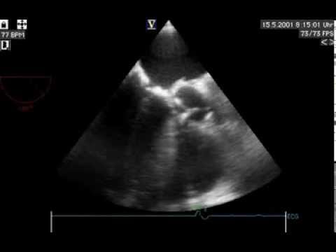
Video 16.4 Echocardiographic exclusion of alternative cardioembolic sources.
Video 16.5
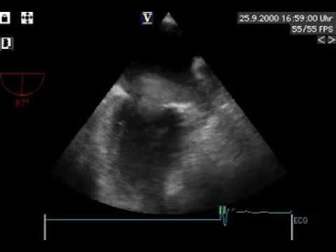
Video 16.5 Echocardiographic exclusion of alternative cardioembolic sources.
Video 16.6

Video 16.6 Echocardiographic exclusion of alternative cardioembolic sources.
Video 16.7.1

Video 16.7.1 Guidance of transseptal puncture.
Video 16.7.2

Video 16.7.2 Guidance of transseptal puncture.
Video 16.8
Video 16.8 Wiring of the left upper pulmonary vein and introduction of the pigtail catheter.
Video 16.9
Video 16.9 Wiring of the left upper pulmonary vein and introduction of the pigtail catheter.
Video 16.10
Video 16.10 Introduction of the sheath.
Video 16.11
Video 16.11 Introduction of the sheath.
Video 16.12

Video 16.12 Introduction of the device and deployment of the distal lobe.
Video 16.13

Video 16.13 Deployment of the proximal part of the device.
Video 16.14
Video 16.14 Stability test.
Video 16.15
Video 16.15 Stability test.
Video 16.16

Video 16.16 Release of the device.
Video 16.17

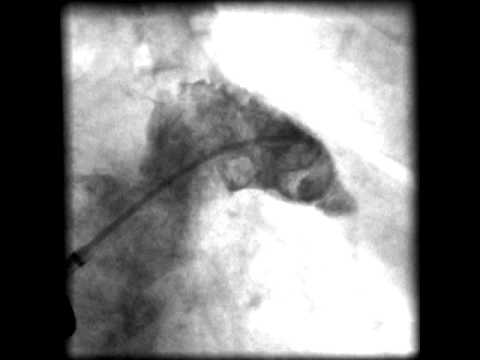
Video 16.17 Angiographic control.
Video 16.18
Video 16.18 Angiographic control.
Video 16.19

Video 16.19 Safety issues. Includes information on thrombus on sheath, thrombus on PLAATO device, small pericardial effusion, and thrombus on AGA cardiac plug device.
Video 16.20

Video 16.20 Safety issues. Includes information on thrombus on sheath, thrombus on PLAATO device, small pericardial effusion, and thrombus on AGA cardiac plug device.
Video 16.21
Video 16.21 Safety issues. Includes information on thrombus on sheath, thrombus on PLAATO device, small pericardial effusion, and thrombus on AGA cardiac plug device.
Video 16.22

Video 16.22 Safety issues. Includes information on thrombus on sheath, thrombus on PLAATO device, small pericardial effusion, and thrombus on AGA cardiac plug device.
Video 17.1

Video 17.1 Incision. One approach to skin incision is described.
Video 17.2

Video 17.2 Crossing a venous obstruction with a 5 Fr dilator. A stenotic subclavian vein is crossed using a 5 Fr dilator and Glidewire.
Video 17.3

Video 17.4
Video 17.4 Removal of an ICD lead with a laser sheath. Detailed example of extraction of an ICD lead from a dual chamber system utilizing a laser sheath.