
Videos from Interventional Cardiac Electrophysiology
Video 26.1

Video 26.1 Noncontact map.
Video 34.1
Video 34.1 Three-dimensional (3D) atrial figure. The figure was constructed from two-dimensional (2D) cross-sectional images of the atria, imported from magnetic resonance imaging (MRI) images of the human heart. The epicardial and endocardial surfaces were plotted on the MRI images, and the 3D images of the epicardial and endocardial features were reconstructed on a computer.
Video 34.2

Video 34.2 Intraoperative mapping of atrial tachycardia (AT) using an electroanatomical mapping system (Carto, Biosense Webster/Johnson & Johnson, Diamond Bar, CA). The patient was a 33-year-old female who had been suffering from a persistent AT from the age of 5 years old.
Video 34.3
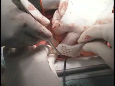
Video 34.3 Intraoperative mapping of atrial fibrillation (AF) using template-type electrodes. Three silicone templates carrying a total of 253 electrodes were placed onto the posterolateral left atrium (LA), superior LA, and lateral right atrium (RA). The curved surfaces of the atria were copied to the templates in order to fit those snugly to the atrial epicardium.
Video 34.4

Video 34.4 Atrial activation during atrial fibrillation (AF): repetitive activations arising from the pulmonary veins (PVs) and fibrillatory conduction to the right atrium (RA). The atria are seen from the superior aspect, as if being observed cranially. Repetitive activations arise from 2 different left atrial (LA) regions adjacent to the right and left superior PVs.
Video 34.5

Video 34.5 Atrial activation during atrial fibrillation (AF): reentrant activations in the lateral right atrium (RA). The map represents the lateral aspect of the RA. There were at least 2 reentrant circuits in the lateral RA. One was in the middle of the lateral RA and the other in the RA appendage.
Video 34.6

Video 34.6 Verification of a conduction block. After the left atrial (LA) antrum was circumferentially ablated bilaterally to isolate the right and left pulmonary veins (PVs) from the LA by means of a bipolar radiofrequency ablation device, atrial fibrillation was defibrillated if needed, and the conduction block across the ablation lines was tested by pacing each PV.
Video 34.7

Video 34.7 Mapping and ablation of active ganglionated plexi (GP). High-frequency stimulation is delivered onto the anatomic GP location to determine the active GP. Active GP is defined as the GP site with a significant vagal reflex, such as temporary asystole or a decrease of 50% in heart rate during stimulation.
Video 34.8

Video 34.8 Intraoperative use of the electroanatomical mapping system. The ventricular epicardium is mapped by roving the NaviStar catheter electrode directly around on the epicardium to simultaneously record the local electrograms and location of the electrode. Ventricular tachycardia (VT) is induced by programmed electrical stimulation using the implanted defibrillator.
Video 39.1

Video 39.1 The commonly successful slow pathway ablation site. The right anterior oblique view (A) and left anterior oblique view (B) show the position of the ablation catheter, which is placed at the posterobasal area of Koch's triangle.
Video 40.1A

Video 40.1A CS angiography (balloon occlusion technique) in the RAO (A) and LAO (B) projections, demonstrating a CS diverticulum. Notice vigorous contraction of the diverticulum, indicating a muscular chamber.
Video 40.1B

Video 40.1B CS angiography (balloon occlusion technique) in the RAO (A) and LAO (B) projections, demonstrating a CS diverticulum. Notice vigorous contraction of the diverticulum, indicating a muscular chamber.
Video 41.1

Video 41.1 Demonstration of reentry around the mitral annulus in a 57-year-old man with muscular dystrophy and spontaneous atrial tachycardia. A propagation map of the LA obtained with the Ensite Velocity system is displayed in the LAO orientation. Counterclockwise reentry is demonstrated around the mitral annulus.
Video 42B.1

Video 42B.1 Carto map showing the ablation catheter approaching the LSPV os to target specific PV potentials. The catheter manipulation is via Stereotaxis magnetic navigation. The LSPV has two distal branches, which are cut out in addition to the true os where the Lasso is sitting. The overall voltage of the LA is normal.
Video 42B.2

Video 42B.2 Carto map showing the ablation catheter moving along the anteroinferior aspect of the LIPV os. During the rotation of the map, the marked ablation points can be seen surrounding the LSPV and part of the LIPV ostia.
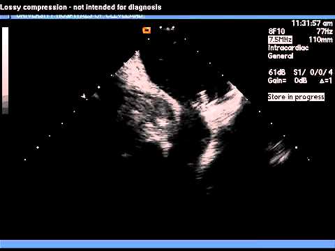
Video 42B.3

Video 42B.3 Intracardiac echocardiography movie showing the Lasso positioned at the os of the LSPV os (the LIPV lies below). There are small bubbles from the ablation catheter, which is at the superior rim of the LSPV os.
Video 42B.4
Video 42B.4 Intracardiac echocardiography movie showing the Lasso positioned at the LSPV os (the LIPV lies below). There are small bubbles from the ablation catheter, which is at the carina between the LSPV and LIPV.
Video 46.1

Video 46.1 The onset of RFA at the earliest Purkinje source of the ectopy-initiating VF triggers short-lasting bursts of polymorphic VT/VF. They gradually become infrequent and eventually disappear during RF application with the elimination of the ectopic beats.
Video 46.2

Video 46.2 The Purkinje potential just precedes the QRS complex, less than 15 ms, and appears fused with the early part of the local ventricular EGM in sinus rhythm. During clinical ectopy, the sharp Purkinje potential clearly precedes both the QRS complex and the local ventricular EGM, confirming that the Purkinje network is the trigger/source of the ectopic beat.
Video 49F.1

Video 49F.1 Stepwise approach hybrid AF.
Video 53.1
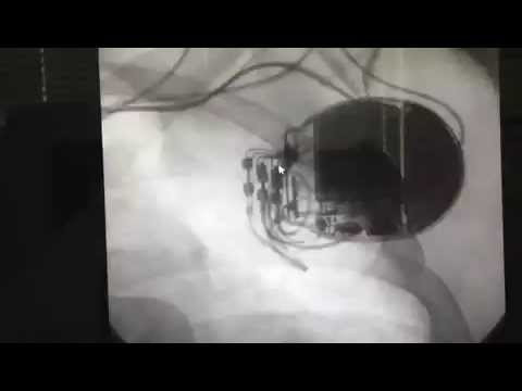
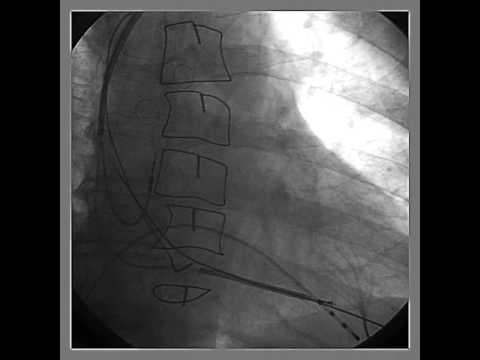
Video 53.1 Fluoroscopy showing a 4-lead implantable defibrillator system for multisite pacing in the right atrium and biventricular pacing and defibrillation back up in a 40-year-old patient with refractory congestive heart failure class 3, dilated cardiomyopathy, and refractory persistent atrial fibrillation after pulmonary vein ablation and antiarrhythmic drug therapy.
Video 54.1
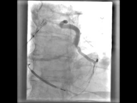
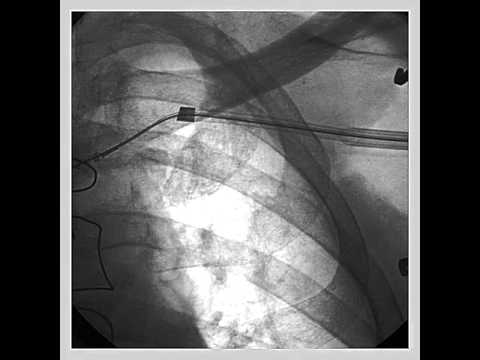
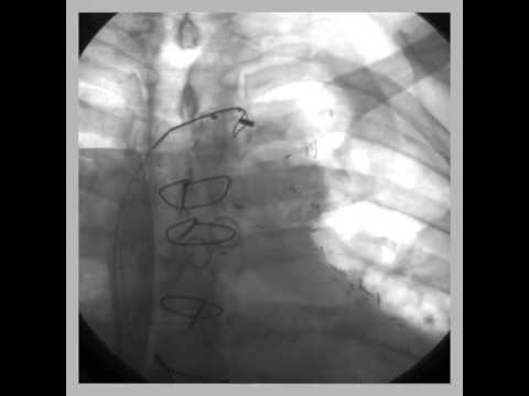
Video 54.1 In this video of a balloon occlusive coronary venous angiogram, the balloon partially obstructs the ostium of a lateral vein. This can sometimes be avoided by performing a pre-angio "puff" prior to balloon inflation.
Video 54.2

Video 54.2 This cine loop of a balloon occlusive retrograde venous angiogram shows an unsteady balloon catheter. Such to-and-fro motion can cause vessel damage and dissection. Source: Courtesy of Dr. Jagmeet P. Singh, MD, DPhil.
Video 54.3

Video 54.3 High-speed rotational coronary venous angiogram over a 110-degree arc from LAO 55 degrees to RAO 55 degrees at a rate of 30 frames per second.
Video 56.1
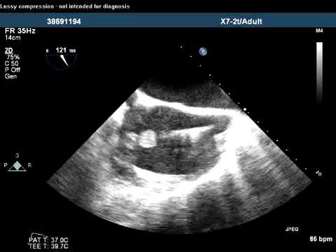
Video 56.1 Large (greater than 2 cm) vegetations attached to the tricuspid valve and device leads are seen by transesophageal echocardiography.
Video 56.2
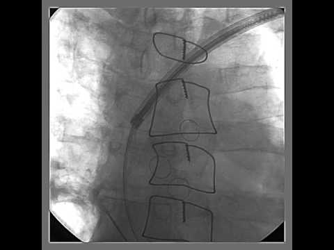
Video 56.2 Cinefluoroscopy 3 days after implantation of a CRT-D system shows dislodgement of the coronary sinus-left ventricular lead, which takes the course into the right ventricle to main right pulmonary artery trunk.
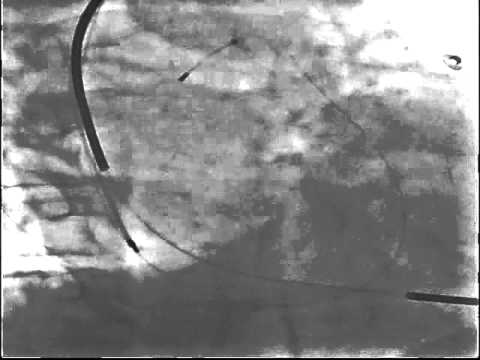
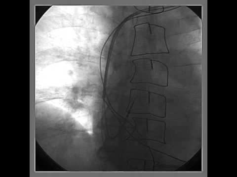
Video 56.3

Videos 56.3-56.5 Percutaneous pericardiocentesis was performed in a thin, elderly female who developed pericardial effusion and cardiac tamponade after impla...
Video 56.4
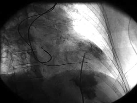
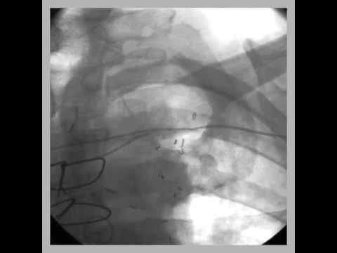
Videos 56.3–56.5 Percutaneous pericardiocentesis was
performed in a thin, elderly female who developed pericardial effusion and cardiac tamponade after implantation of a dual-chamber pacemaker. Pericardial access was obtained from subxiphoid approach. A guidewire was inserted up to the level of pericardial reflection underfluroscopy (clip 1), injection of dye into the pericardium confirmed pericardial effusion (clip 2), and after removal of blood from the pericardial space, the pericardial drain was left in situ (clip 3).
Video 56.5

Videos 56.3-56.5 Percutaneous pericardiocentesis was performed in a thin, elderly female who developed pericardial effusion and cardiac tamponade after implantation of a dual-chamber pacemaker. Pericardial access was obtained from subxiphoid approach.
Video 60.1
Video 60.1 Initial AP cine demonstrating three bipolar leads in typical locations. Note that the leads appear to move as one unit through the left brachiocephalic vein, where there is lead-to-lead binding.
Video 60.2
Video 60.2 A typical coronary sinus lead extraction is depicted. The lead is removed with direct traction, with no evidence of binding; 90% of coronary sinus leads are removed in this way, with 10% requiring the use of extraction tools.
Video 60.3
Video 60.3 After the atrial lead is removed, the laser is gently advanced over the high-energy lead. The bevel of the laser is turned toward the inside of th...
Video 60.4

Video 60.4 With heavy binding in the subclavian area, the outer sheath (Teflon®) is advanced over the laser to break up heavy fibrosis, to expand the lumen, and to reduce binding of the laser with surrounding scar tissue. The outer sheath is advanced just past the laser, with the bevel toward the inside of the curve.
Video 60.5

Video 60.5 The laser continues slow advancement over the proximal high-energy coil. The coil gradually unwinds, due to the appropriate tension on the lead to maintain a stable rail. The laser bevel is oriented toward the inside of the curve.
Video 60.6

Video 60.6 With heavy binding in the SVC, the outer sheath is advanced to break up the binding site. The bevel is oriented toward the inside of the curve, and there is substantial traction on the lead to pull it away from the SVC wall.
Video 60.7
Video 60.7 Use of the inner and outer sheaths together breaks up the last fibrotic area, and the lead is removed in its entirety. Bevel orientation and traction are maintained.
Video 60.8
Video 60.8 Two FineLine coradial leads. The coils on one lead are stretched, not allowing a locking stylet to pass. The other lead is completely fractured and intravascular, precluding a superior approach for removal.
Video 60.9

Video 60.9 The stretched ventricular lead has been removed to the level of the clavicle. It binds here due to calcification around the entry site. A metal dilator is unable to pass the calcification, and the lead ultimately breaks off here.
Video 60.10

Video 60.10 A needle’s eye snare is used femorally to remove the remnant atrial lead in its entirety.
Video 60.11
Video 60.11 The remnant ventricular lead segment is grasped with a large snare, also from the femoral approach.
Video 60.12

Video 60.12 The ventricular lead remnant is pulled into the femoral extraction sheath.